6. Design
Design turns solved moments into reinforcement and checks the section against
the selected code. It runs in the browser from the solved results, so changing
the code or a limit re-evaluates without re-solving.
This chapter documents the codes and defaults, the calculation behind each
check, the strip/band workflow, and worked numbers you can reproduce.
6.1 Design code and defaults
Settings → Design sets the model's design parameters; applying it stamps them
onto the project (design_params) and the footer code badge.
| Setting | Default (EC2) | AS 3600 | ACI 318 | CSA A23.3 |
|---|---|---|---|---|
| Design code | EC2 (EN 1992-1-1) | AS 3600-2018 | ACI 318-19 | CSA A23.3-19 |
| f′c | 32 MPa | 32 | 30 | 30 |
| fy | 500 MPa | 500 | 420 | 400 |
| Cover top | 25 mm | 25 | 40 | 40 |
| Cover bottom | 25 mm | 25 | 20 | 20 |
| Default bar | H12 | N12 | #4 | 15M |
| Max spacing | 200 mm | 200 | 200 | 200 |
| Crack width limit | 0.3 mm | 0.3 | 0.3 | 0.3 |
| Steel stress limit | 300 MPa | 300 | 300 | 300 |
| Crack strain kt | Long-term 0.4 | ignored | ignored | ignored |
| Shrinkage strain | – | 600 µε | – | – |
| Service moments | No Wood-Armer | No Wood-Armer | No Wood-Armer | No Wood-Armer |
Switching code stamps its canonical defaults when the current value is within
5 % of the previous code's canonical value - deliberate custom values survive.
Per-strip overrides (cover, bars, w_max, sigma_max, code, …) always win over
the global defaults.
Wood–Armer: strength design always uses Wx = abs(Mx) + abs(Mxy) and
Wy = abs(My) + abs(Mxy). The Service moments setting chooses whether the
service checks (crack width, steel stress) also use Wood–Armer or the actual
Mx/My/Mxy.
Limit state comes from the active combination (SLS/ULS/Auto). The
service factor for crack/stress checks is 1.0 for SLS results and 0.65 when the
moments are ULS (i.e. service moment ≈ 0.65 × ULS moment).
6.2 Flexure
Rectangular stress-block design, iterated 2–6 passes:
As0 = M / (φ fy 0.95 d)
repeat:  a = As fy / (α fc b)
         z = d − β a / 2
         As = M / (φ fy z)
capacity φMn = φ As,prov fy z
b = 1000 mm per metre width. Parameters per code:
| Code | α | β | φ |
|---|---|---|---|
| EC2 (default) | 0.85 | 1.0 | 1.0 |
| AS 3600 | α₂ = clamp(0.85 − 0.0015 f′c, 0.67, 0.85) | γ = clamp(0.97 − 0.0025 f′c, 0.67, 0.85) | 0.85 |
| ACI 318 | 0.85 | 1.0 | 0.9 |
| CSA A23.3 | 0.65 × clamp(0.85 − 0.0015 f′c, 0.67, 0.85) | 1.0 | 0.85 |
d is measured to the bar centroid: d = t − cover − bar/2. If the section is
over capacity (z ≤ 0) the required steel is reported as infinite and the
element/plan is flagged (magenta in the steel map). There is no
doubly-reinforced or redistribution calculation; increase the thickness or
provided steel instead.
6.3 Minimum steel
Governing steel = max(flexure, code minimum, crack-control minimum).
| Code | Minimum per metre width |
|---|---|
| EC2 9.3.1.1 | max(0.26·fctm/fyk, 0.0013) · b · d, fctm = 0.30 f′c^(2/3) |
| AS 3600 9.1.1 | 0.20 · (D/d)² · fct.f/fsy · b · d, fct.f = 0.6√f′c |
| ACI 24.4.3.2 | 0.0018 · Ag |
| CSA 7.8.1 | 0.002·Ag (fy ≤ 400), else 0.0015·Ag |
| Crack control (all codes) | kc·k·fct,eff·Act / fyk with kc = 0.4, k = 1.0, fct,eff = 0.30 f′c^(2/3), Act = 0.5 t |
The reported minSource tells you whether flexure or the crack/shrinkage
minimum governed.
6.4 Maximum bar spacing
| Code | Limit |
|---|---|
| EC2 9.3.1.1(3) | min(3h, 400 mm) |
| AS 3600 9.1.3 | min(2D, 300 mm) |
| ACI 8.7.2.2 | min(2h, 450 mm) |
| CSA 7.4.1.3 | min(2h, 500 mm) |
Plus the user Max spacing setting (default 200 mm) caps the selected
spacing.
6.5 One-way shear
Demand is the peak Q = abs(Qx cosθ + Qy sinθ) along the strip.
| Code | Resistance per metre |
|---|---|
| EC2 6.2.2 | k = min(1+√(200/d), 2); vRd,c = max(0.18/1.5·k·(100 ρl f′c)^(1/3), vmin), vmin = 0.035 k^1.5 √f′c; VRd,c = vRd,c · d (d in m, VRd,c in kN/m) |
| AS 3600 8.2.4 | fcv = min(f′c^(1/3), 4); β1 = max(1.1(1.6 − do/1000), 0.8); Vuc = β1·bv·do·fcv (φ = 0.75 applied), bv = 1000 mm |
| ACI 318-19 22.5.5 | λs = min(√(2/(1+0.004d)), 1); vc = min(0.66 λs ρw^(1/3) √f′c, 0.42 √f′c); φVc = 0.75 vc d |
| CSA 11.3 | dv = max(0.9d, 0.72h); β = 230/(1000+dv); Vc = 0.65 β √f′c dv 1000 |
ρl or ρw is taken as provided-steel ratio clamped to [0.0008, 0.02], and per
the code's d limits for AS 3600 (do). Utilisation = V*/(φV) ≤ 1.
One-way shear rarely governs slabs; it matters for thick transfer slabs and
bands.
6.6 Punching shear
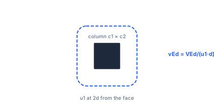
The check runs for every column against the active result set. Demand comes
from the column stub's axial force and simultaneous bending moments at slab
level.
Control perimeter and offset
| Code | Offset | Shape |
|---|---|---|
| EC2 | 2d | rectangular, round corners |
| AS 3600 | dom/2 | round corners |
| ACI / CSA | d/2 | square corners |
Circular columns: u = π(c + 2·fd); rectangular rounds: 2(a+b) + 2π·fd;
squares: 2(a+b) + 8·fd. The perimeter is clipped to the slab polygon
minus openings, and classified corner (≥ 45 % cut), edge (≥ 15 %) or
interior. d = t − (cover + bar/2); a drop panel or band beam over the column
raises the local head depth used.
Resistance
| Code | vRc (MPa) |
|---|---|
| EC2 6.4.4 | max(0.18/γc·k·(100ρl f′c)^(1/3), vmin), γc = 1.5, k = min(1+√(200/d), 2) |
| AS 3600 9.3.2 (φ = 0.7) | φ·min(0.17(1 + 2/βh)√f′c, 0.34√f′c) |
| ACI 318-19 22.6.5 (φ = 0.75) | 0.75·min(0.33 λs √f′c, 0.33 λs(1 + 2/β)√f′c, 0.25 λs(2 + αs d/bo)√f′c), √f′c ≤ 8.3 MPa, αs = 40 interior / 30 edge / 20 corner |
| CSA 13.3.4 (φc = 0.65) | 0.65·min(0.19(1 + 2/βc)√f′c, 0.19(1 + αs d/bo)√f′c, 0.38√f′c), αs = 4/3/2 |
ρl is averaged over the column width plus 3d each side, capped at 0.02, taken
from provided strip bars where available.
Moment transfer
- EC2:
v = V/(u d) + Σ k·M·e/(W d)with k from Table 6.1 (0.45/0.60/0.80
by aspect ratio) - biaxial. - AS 3600 Cl 9.3.4(a):
v* = V*/(u dom) + Mv*/(8 a dom²),a = min(colA, colB) + d. - ACI / CSA: closed-form polar properties
Ac, Jc, γv, cfor
interior/edge/corner; each axis checked separately; corner moments reduced by
V·e.
Reading the result
The Σ summary lists V*, M*, u₁, v*, vR, utilisation and PASS/
FAIL. Colour thresholds: green < 90 %, yellow 90–100 %, red ≥ 101 %. Typical
outcomes: 400 mm columns and 200 mm slabs at ~10 kPa UDL give utilisation
around 0.7–1.0 - punching is what sizes flat plates.
Worked anchor (slab-punching verification model): 100 kN column load,
slab 200 mm, C32, 300 mm interior column, EC2 defaults. Hand check with
d = 200 − 25 − 6 = 169 mm and the rounded-perimeter form used by the check
(radius 2d):
u1 = 2(c1 + c2) + 4πd = 2(0.3 + 0.3) + 4π(0.169)
   = 1.200 + 2.124 = 3.324 m
vEd = VEd/(u1 d) = 100/(3.324 × 0.169) = 0.178 MPa
reproducing the published u₁ = 3.324 m, vEd = 0.178 MPa. For edge and
corner columns the perimeter is clipped by the slab boundary; read the
computed u₁ from the summary rather than scaling the interior value.
6.7 Crack width
Service moment Ms = serviceFactor × M* (1.0 for SLS sets, 0.65 for ULS). The
section is always evaluated cracked: transformed section solves
½ b x² = αe As (d − x), αe = Es/Ecm,
Ecm = 22000·((f′c+8)/10)^0.3, z = d − x/3,
hc,ef = min(2.5(t−d), (t−x)/3, t/2), ρeff = As/hc,ef.
| Code | Check |
|---|---|
| EC2 7.3.4 | sr,max = 3.4c + k1 k2 k4 φ/ρp,eff (implemented with k1=0.8, k2=0.5, k4=0.425); εsm − εcm = max((σs − 0.4·fctm/ρeff(1+αe ρeff))/Es, 0.6σs/Es); wk = sr,max(εsm−εcm) ≤ w_max; tension-stiffening coefficient 0.4 long-term / 0.6 short-term |
| AS 3600 8.6.2.3 / 9.4.2 | sr,max = 3.4c + 0.3 k1 k2 φ/ρeff with k1=0.8, k2=0.5; a fixed 0.6 stiffening coefficient plus the shrinkage strain εcs (default 600 µε); spacing limit s ≤ min(2D, 300) at σs |
| ACI 318-19 24.3.2 | fs = 2/3 fy; s ≤ min(380(280/fs) − 2.5cc, 300(280/fs)); wk shown is the EC2-style estimate |
| CSA 10.6.1 | z-factor fs∛(dc A) ≤ 30 000 N/mm interior (25 000 exterior), fs = 0.6 fy, dc = cover + φ/2, A = 2 dc s |
Cracking moment Mcr = 0.30 f′c^(2/3) · 1000 t²/6 kN·m/m is reported for
reference. Default limit w_max = 0.3 mm, overridable per strip.
6.8 Steel stress and deflection
Steel stress σs = Ms/(As,prov z), limit σs ≤ 0.6 fy and the user
setting (default 300 MPa).
Deflection limit per strip: L/250 (AS 3600 Table 2.3.2, EC2 7.4.1(4)) or
L/240 (ACI Table 24.2.2, CSA Table 9.2); demand is the peak |uz| along the
strip. Long-term deflection comes from the solver time model
(§4.4), not from a multiplier.
6.9 Anchorage and lap
EC2 8.4.3:  lb = fy db / (4 fbd),      fbd = max(1, 0.20 f′c^(2/3))
AS 3600:    lb = 0.5 fy db / √f′c
ACI 25.4:   lb = 0.43 fy db / √f′c
CSA 12.2:   lb = 0.45 fy db / √f′c
minimum lb = 12 db
method factors: straight 1.0, hooked/cogged 0.70, headed 0.60
lap = max(12 db, lb × factor),  factor: AS 1.3, ACI 1.0, CSA 1.3, EC2 1.3
Strip anchorage compares the available run (plus an adjacent strip marked
continuous, within 5° and a ≤ 0.25 m gap) against lb or the lap length.
6.10 The design workflow
Element reinforcement maps
For every shell element the program computes Wood–Armer moments (top and
bottom), effective depths, required/minimum/crack steel and the governing
value; these populate the B1/B2/T1/T2 maps and the steel tonnage. A global bar
lattice with standard spacings (100/150/200/250/300 mm) and bars N10–N40 backs
the marking plans.
Design strips
- Draw strips along the column and middle strips (or use automatic centre
strips and + Add strips). - Assign bars manually, or leave Auto and click Size to limits in
Properties → Limits; the program binary-searches the lightest standard
arrangement that satisfies the crack and steel-stress limits on the solved
moments. - Read diagrams (⌗) and the global wk/σs views; iterate bars/widths.
- Use Copy from strip… to propagate a good arrangement.
The strip Design basis chooses average (width-averaged peak, default) or
peak (envelope) moments. One-way spans design only the spanning layer fully;
the other layer receives the minimum.
Bands (edge beams)
Bands use their own beam design: min steel per code (EC2 9.2.1.1, AS 3600
8.1.6.1, ACI 9.6.1.2, CSA 10.5.1.2), suggestBars picks the lightest
arrangement from N10–N40 with clear spacing ≥ max(25 mm, db), and
requiredAsService solves the crack/stress limits. Peak or face-of-support
moments are selectable.
Current flags
The per-strip design check list and the full Member Design Calculations
sheet are implemented but hidden behind an internal flag; the reachable design
path is Size to limits + the strip diagrams, and the punching summary/report.
The calculation engine described above is what those paths use.
6.11 Worked design example
Model col-four-udl (8 × 8 m, t = 200 mm, C32, four 300 mm columns at
±3 m, q = 10 kPa, EC2 defaults, no self weight except the applied UDL).
- From the elastic SLS run, the peak banded Mx near a column line reads
≈ 16 kN·m/m (this example is chosen for round numbers; read your own). - Flexure (EC2):
d = 200 − 25 − 6 = 169 mm.
As ≈ M/(φ fy z)with z ≈ 0.95d = 161 mm →
As = 16e6 / (1.0 × 500 × 161) ≈ 199 mm²/m. - Minimum (EC2):
fctm = 0.30 × 32^(2/3) = 3.03 MPa;
As,min = max(0.26 × 3.03/500, 0.0013) × 1000 × 169 ≈ 266 mm²/m-
minimum governs. - Crack-control minimum:
0.4 × 1.0 × 3.03 × (0.5×200)/500 × 1000 ≈ 242 mm²/m< 266. - Choose N12 @ 300 = 377 mm²/m (≥ 266) - or let Size to limits pick.
- Max spacing: EC2
min(3×200, 400) = 400 mm, user cap 200 mm → @200
or closer required; choose N12 @ 200 = 565 mm²/m if the cap is 200 mm. - Punching: check the ◉ view; scale to your column/load until
utilisation < 1.0, adding a drop panel or thickening if needed. - Crack width: with N12 @ 200,
ρeff ≈ 565/(hc,ef); the wk diagram
should sit below 0.3 mm - verify in the wk view.
The steps are the same for any code; only the parameters in §6.2–6.7 change.
6.12 Limitations
- No moment redistribution, no doubly-reinforced design, no shear
reinforcement / stud rails in the punching check (concrete resistance only). - Punching checks the column perimeters only; wall/beam ends on columns are
not separate perimeters. - Crack width uses the EC2-format formula for ACI as an estimate; CSA uses the
z-factor. - The bar marking plans reflect strips, not the element-by-element lattice;
use them as layout guidance and the B/T maps for required areas. - The per-strip check list and member calculation sheet are currently hidden
in the UI (see above).
→ Next: Chapter 7 - Soil & piles