2. Modelling
This chapter is the reference for every modelling tool, its dialog fields and
defaults, the editing and selection mechanics, the material library, the grid
and setout system, validation, and the meshing rules applied before analysis.
All modelling is done in slab mode (the only mode); the semantic model is
stored under FloorModel and saved with the project.
2.1 Tools at a glance
| Toolbar button | Tool | Default unit | Panel fields (defaults) |
|---|---|---|---|
| Slab | polygon region | m | Thickness 0.2 · Elevation 0 · f′c 32 · E 30 GPa · ν 0.2 · ρ 2400 · Mesh 1.0 · Span: Two-way |
| Opening | rectangle cut-out | – | (none) |
| Column | column stub or point support | m | Type Column · Rect 0.3 × 0.3 · Z↓ 3 · Z↑ 3 · Base Fixed · Top None · k 10 000 kN/m (spring) · Stiffness 100 % |
| Pile | pile with springs | m | Axial k 100 000 kN/m · Lateral 0 · d 0.6 · L 8 · EI 0 (auto) · Rot k 0 · Head Fixed · k 10 000 kN·m/rad · Soil layers… |
| Soil zone | Winkler mat rectangle | kN/m³ | Subgrade k 30 000 |
| Strip | design strip | m | Width 3 · bars/spacings Auto · Cover 30 mm |
| Wall | wall / line support | m | Type Wall · Width 0.2 · Height 3 · Extent Below · Base Pinned · k 10 000 kN/m · Support every base node |
| Beam | edge beam (band) | m | Width b 0.3 · Depth h 0.6 |
| Vertical plate | step web between levels | m | Thickness t 0.3 |
| Drop panel | local thickening | m | Thickness t 0.45 |
| Grid line | manual setout line | m | click X line, Shift-click Y line |
| Create grid | grid generator | m | rows of Spacing × Count, start ordinates, setouts |
| Dimensions | show grid dimensions | – | toggle |
| Measure | permanent dimension | m | two clicks |
| Edit slab shape | boundary node editor | m | Offset 0.3 · Edges All |
| Material library | grades and custom materials | – | per-grade E, ν, ρ, fy |
While a drawing tool is active its options appear in a small draggable panel
(titled Slab, Column, Wall, …). The ×/Done button hides the panel
but keeps the tool armed - the next canvas click continues drawing. Press
Esc to leave the tool.
2.2 Slabs
A slab is a flat polygon at one elevation and one thickness. All structural
action starts from slabs.
Slab tool fields
| Field | Unit | Default | Range / step | Notes |
|---|---|---|---|---|
| Thickness | m | 0.2 | ≥ 0.05, step 0.01 | one thickness per slab; use drop panels/steps otherwise |
| Elevation | m | 0 | step 0.5 | top-of-slab reference for loads and supports |
| Concrete grade | – | Custom | grades of the active code | fills f′c, E and ρ below from the library |
| Concrete f′c | MPa | 32 | ≥ 12, step 1 | characteristic strength used for cracking and design |
| Span behaviour | – | Two-way | Two-way / One-way along X / One-way along Y | one-way designs the spanning direction fully and gives minimum steel across it |
| E | GPa | 30 | ≥ 1, step 1 | elastic modulus (30 GPa = 30 000 MPa); stored in Pa |
| Density | kg/m³ | 2400 | ≥ 1 | self weight = ρ·t·9.81/1000 kN/m² |
| Mesh size | m | 1.0 | ≥ 0.1, step 0.1 | target element size; feature lines always mesh |
| Poisson ν | – | 0.2 fixed | – | not exposed for new slabs (0.2) |
Drawing a slab
- Click the Slab tool.
- Click each polygon corner. Corners snap to the grid/nodes per the Grid &
Snap settings. - Finish with double-click,
Enter, or by clicking within 0.5 m of the
first corner. Fewer than 3 corners is rejected with
slab outline needs at least 3 corners. - The slab gets the next name
S<n>and a running numeric id. The status line
suggests click MESH to generate the discretized mesh.
Editing
- Move a corner: click a corner handle and drag it (snaps live). On release
the status reportsCorner n moved to (x, y); the mesh/results are
invalidated. - Add a corner: open Edit slab shape for the slab and click a
+
handle on an edge. - Delete a corner: open Edit slab shape, click the corner, then
Delete node (or pressDelete). A polygon must keep ≥ 3 corners
(A polygon needs at least three corners). - Offset edges: in Edit slab shape: distance (default 0.3 m, positive
outward), edge selection All edges or Edge i (L m), then Apply
offset. While the editor is open, every edge shows its number next to it
in the canvas, and the edge picked in the dropdown is highlighted on the
slab - the pick stays selected after each offset so repeated nudges keep
working. Neighbours stretch to remain connected. - Properties: Elevation, Thickness, Concrete grade, Span behaviour, E, ν,
Density, Mesh size.
Slab shape editor (Edit slab shape)
| Control | Default | Behaviour |
|---|---|---|
| Slab select | first slab | pick the slab to edit |
| Offset distance (m) | 0.3 | + moves edges outward, − inward |
| Edges | All edges | or one edge only; the picked edge highlights in the canvas and the pick is kept after each offset |
| Apply offset | – | moves the chosen edges; errors: No slab to offset, Type an offset distance first, Offset too large for this shape - try a smaller distance |
| Delete node | – | disabled until a corner is selected; minimum 3 corners |
| Footer | – | N boundary nodes · node k selected |
Touching same-elevation slabs mesh together automatically: shared edge
segments and common coordinates merge within 1e-6 m, and the connected group
adopts the finest mesh size of its members.
2.3 Openings
Openings are axis-aligned rectangles cut from one slab. Steps:
- Click Opening, then click two opposite corners.
- The rectangle centre must lie inside a slab, else
Opening must be drawn inside a slab region. - The opening is stored against that slab and named
Opening <n>.
Validation at mesh/analysis time: the rectangle must be four-sided and
axis-aligned, lie fully within its slab, and not cover the entire slab.
Point loads inside an opening are rejected (point load N lies within a slab opening); area loads over openings apply only to elements outside them.
2.4 Columns and point supports
Column tool fields
| Field | Unit | Default | Range | Notes |
|---|---|---|---|---|
| Type | – | Column | Column / Point support | a point support is a restraint only - no stub stiffness, no self weight |
| Shape | – | Rectangular | Rectangular / Circular | hidden for point supports |
| b (width) | m | 0.3 | ≥ 0.1, step 0.05 | rectangular |
| h (depth) | m | 0.3 | ≥ 0.1, step 0.05 | rectangular |
| d (diameter) | m | 0.3 | ≥ 0.1, step 0.05 | circular |
| Z↓ under | m | 3 | ≥ 0 | stub below the slab elevation |
| Z↑ over | m | 3 | ≥ 0 | stub above the slab elevation |
| Base / support | – | Fixed | Fixed / Pinned / Spring / None | for point supports: Pinned / Fixed / Vertical spring (defaults to Pinned if free) |
| Spring k | kN/m | 10 000 | ≥ 0 | vertical spring; only for Spring |
| Top | – | None | None / Pinned / Fixed | restraint at the stub top |
| Stiffness (%) | % | 100 | 1–500, step 5 | scales the stub's Iy, Iz and J only |
Place with a single click. The status line reports the coordinates and Z range
(Column at (x, y), z = a → b) or the support type and spring.
How columns are modelled
- A column is a vertical beam stub of the given section and heights,
meshed as a chain of beam elements (E = 30 GPa, ν 0.2, ρ 2400 unless the
slab material applies). It carries self weight through its density and is
included in the vertical load path. - Its stiffness matrix uses Iy = w·d³/12, Iz = d·w³/12 and a Timoshenko
rectangular torsion constant; Stiffness (%) scales all three. - A point support restrains the nearest slab node
(withinmax(0.2, 0.75 × mesh size)) in Z (fixed/pinned/spring) with no
section or self weight. - The column top/bottom restraints act on the stub ends; a Top = None
column is laterally stable only through the slab (the solver's in-plane
stabilisation handles it), so use pinning/fixing where the structure
actually provides it.
Bulk edit: select several columns and edit Shape, b, h, d, Z bottom/top,
Bottom/Top boundary and Bending stiffness % together.
2.5 Piles
Pile tool fields
| Field | Unit | Default | Range | Notes |
|---|---|---|---|---|
| Axial k | kN/m | 100 000 | ≥ 0 | vertical head spring Kz |
| Lateral k | kN/m | 0 | ≥ 0 | horizontal head springs Kx = Ky |
| Diameter | m | 0.6 | ≥ 0, step 0.05 | > 0 meshes a shaft of beam elements |
| Length | m | 8 | ≥ 0, step 0.5 | head to tip |
| Bending EI | kN·m² | 0 | ≥ 0 | 0 = automatic from diameter, concrete E = 30 GPa |
| Rotational k | kN·m/rad | 0 | ≥ 0 | toe rotational restraint |
| Head restraint | – | Fixed (moment connected) | Fixed / Pinned / Rotational spring | connection to the slab |
| Head spring k | kN·m/rad | 10 000 | ≥ 0 | only for Rotational spring |
| Soil layers | – | – | opens the layer editor | distributed shaft springs |
Placement: one click; the head sits at the host slab elevation and the tip at
head − length. Drawing a pile switches the model mode to pile_supported.
How piles are modelled
- If Diameter > 0 a vertical beam chain is generated (segment length ≈ 1 m,
at most 20 segments), EI auto-derived from the diameter unless you give a
value. - Head springs:
Kx = Ky = Lateral k,Kz = Axial k,Krx = Kry = Krz = Rotational k, placed at the tip node. The head link length is 0.05 m; a
pinned head uses a tiny (0.001·I) link stiffness, a rotational spring uses
I = k·L/E. - With Diameter = 0 the pile is a set of head springs only (no shaft).
- Pile soil layers add distributed shaft springs: each meshed shaft node
receivesKx = Ky = LateralK × tributary lengthandKz = Skin × tributary lengthfrom the layer(s) it spans. Layers are global (shared by all piles). - Pile head must land on the generated mesh within 1e-7 m, otherwise
pile N head does not lie on the generated mesh(move the pile or refine the
mesh so a node exists at the head).
Pile soil layers modal
Title Pile soil layers - columns Name, Top (m), Bottom (m),
Lateral k (kN/m/m), Skin (kN/m/m); delete × per row; + Add layer.
New-layer defaults: name Layer <id>; top = previous bottom (first layer top
starts at 0); bottom = top − 5; lateral k 5 000; skin 1 000.
Rules (enforced at validation): top must be above bottom; stiffnesses ≥ 0; at
least one of lateral/skin > 0. Layer elevations are measured in model Z
(elevations, not depth below head). Empty state text: "No layers - pile shaft
support comes from the tip springs in the pile inputs."
See Chapter 7 for the p-y/skin model and worked
numbers.
2.6 Soil zones
Draw with two clicks (rectangle); the panel has one field:
| Field | Unit | Default | Range | Notes |
|---|---|---|---|---|
| Subgrade k | kN/m³ | 30 000 | ≥ 0, step 1 000 | distributed vertical spring stiffness |
| Compression only (no tension) | – | off | – | gap-capable contact; the analysis iterates lifted springs off |
Drawing the first soil zone switches the model to slab_on_ground. Zones
auto-cycle through colours and can overlap; each zone may also display an
allowable bearing value used for the bearing result annotation.
Properties: Name, Subgrade modulus, No tension (compression-only
contact), Opacity slider (0.75 body / 0.2 for light ground), Colour.
Each meshed slab node inside a zone gets Kz = k × tributary area (kN/m).
Rules:
slab_on_groundrequires at least one soil zone; k must be > 0.subgrade modulus must be greater than zero- every zone needs k > 0.
Tick Compression only for no-tension contact; the solver iterates it.
Typical k values (kN/m³): soft clay 5 000–15 000, firm clay 15 000–40 000,
loose sand 15 000–30 000, dense sand 40 000–100 000, rock 200 000+.
See §7.1.
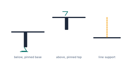
2.7 Walls and line supports
Wall tool fields
| Field | Unit | Default | Range | Notes |
|---|---|---|---|---|
| Type | – | Wall | Wall / Line support | line support = restraint line, no wall plates, no self weight |
| Width | m | 0.2 | ≥ 0.1, step 0.05 | hidden for line support |
| Height | m | 3 | ≥ 0.1, step 0.5 | hidden for line support |
| Extent | – | Below slab | Above slab / Below slab / Both sides | where the wall runs relative to the slab |
| Base restraint / support | – | Pinned (translations) | Free / Pinned / Fixed / Point spring / Line spring | acts at the base of the below-slab run; ignored for above-only walls (they bear on the slab). For line supports this is the support condition (a line support is forced to carry a restraint) |
| Spring k | kN/m | 10 000 | ≥ 0 | Point spring: kN/m at each end; Line spring: kN/m per metre run |
| Support every base node | – | checked | – | unchecked restrains only the two wall corners |
Drawing: two clicks; length ≥ 0.1 m; start and end must lie inside the same
slab. The wall's z_bottom/z_top derive from the extent and height.
How walls behave
- A Wall is meshed with wall plates on the chosen side(s) of the slab,
densified to the local mesh size; material follows the slab unless overridden
in Properties (f′c, E, ν, ρ). - Below-slab run: the base restraint acts at the foundation
(z_bottom): Free, Pinned, Fixed, Point spring or Line spring.
Support every base node applies the restraint along the whole base -
uncheck it to model isolated corner restraints. - Above-only wall: it bears on the slab. Its base edge shares the slab's
mesh nodes, so the Base restraint is ignored (including base springs) and
the wall cantilevers from the slab. The top edge is held only by an explicit
Top restraint (Free / Pinned / Fixed) - use it to tie the wall to the
structure above. This means an above-slab wall never supports the slab, and
the ground/soil springs carry the model as drawn. - A wall spanning both sides meshes below and above with one shared edge:
the base restraint acts atz_bottom, the top restraint atz_top. - Wall springs are vertical only (Kz) in the current implementation; there
is no horizontal soil pressure. - Wall self weight is applied as nodal line loads
(w = width × height × density × 9.81/1000kN/m) unless the wall has an
explicit SelfWeightCase. - Below-slab walls carry no density (their weight is not double-counted
with the ground path); above-slab walls carry it. - A wall's Top line load (kN/m, positive down) and its Load case are
entered in Properties. The load belongs to that case like any other load:
it is drawn and factored only when the case (or a combination containing it)
is active. If the case is left unassigned, the first load case is used.
When wall plates exist, the load is applied at the top edge; otherwise the
load falls back to a slab line load. - A Line support is not meshed: it is a restraint line (fixed/pinned/spring)
on the nearest slab nodes, with no stiffness or weight of its own.
2.8 Edge beams (bands)
The Beam tool draws a band along an edge between two clicks inside the same
slab.
| Field | Unit | Default | Range |
|---|---|---|---|
| Width b | m | 0.3 | ≥ 0.1, step 0.05 |
| Depth h | m | 0.6 | ≥ 0.1, step 0.05 |
The beam hangs below the slab: z_bottom = slab elevation − depth,
z_top = elevation + 0.02; the slab thickness at that location is deducted
from the beam section (D − t) so stiffness and weight are not double counted.
Properties:
| Field | Default | Options |
|---|---|---|
| Width / Depth / Below slab / Above slab | from tool | m |
| Mesh as slab | off | thickened shell strip instead of a beam (for wide shallow bands) |
| Section | Centroid (composite) | Centroid / Mid-plane (composite) |
| Torsion | No-torsion | No-torsion (0.001·J remnant) / Standard |
| Moments | Peak (centreline) | Peak (centreline) / Face of support |
Design along bands uses the band total moment (kN·m, not per metre) and stays
out of the shell moment contour unless B± is enabled in the results pane.
2.9 Drop panels
Two-click rectangle inside a slab; field Thickness t (m, default 0.45,
≥ 0.1). Drop panels thicken the slab locally (element thickness = maximum
covering panel) and their outline becomes a mesh feature line. No extra self
weight beyond the thicker shell volume. Name Drop <n>.
Use them around punching columns, or the local head depth is picked up by the
punching check from either a drop panel or a band beam.
2.10 Vertical plates (steps)
Draw two clicks along the step line between two slabs at different elevations.
| Field | Unit | Default | Range |
|---|---|---|---|
| Thickness t | m | 0.3 | ≥ 0.05, step 0.05 |
Preconditions:
- length ≥ 0.1 m (
Vertical plate length too short); - both slabs must exist under the midpoint
(Vertical plate needs two slabs at different levels under the line (a step)); - both ends must lie over the lower slab
(Plate ends must lie over <low slab name> (the lower slab)); - the step height (upper elevation − lower top) must be ≥ 0.05 m.
The plate closes the vertical face between the slabs, participating in bending
and in the load path.
2.11 Design strips
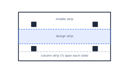
A design strip is a rectangle spanning between two points inside one slab,
over which results are integrated and design is performed.
Strip tool fields
| Field | Unit | Default | Options |
|---|---|---|---|
| Width | m | 3 | ≥ 0.1, step 0.1 |
| Bottom bar | – | Auto | Auto / N10…N40 |
| Bottom spacing | – | Auto | Auto / @100, @150, @200, @250, @300 |
| Top bar | – | Auto | Auto / N10…N40 |
| Top spacing | – | Auto | Auto / @100…@300 |
| Cover | mm | 30 | ≥ 0, step 5 |
Auto fields are not stored - the program sizes them. Drawing requires start
and end inside the same slab and width > 0
(Design strip width must be greater than zero).
Strips are repaired on save/load: endpoints clamp onto the owning polygon and
the width shrinks (binary search) until the strip rectangle lies inside the
slab (default 0.5 m minimum fallback). A strip must also satisfy
design strip must lie fully within its slab region after repair.
Width guidance: a column strip is typically 0.25·L each side of the column
line (total 0.5·L); the middle strip fills the rest of the bay. Draw one strip
per band and per direction, or use + Add strips to materialise the
automatic centre strips the program shows when none exist (one X and one Y
through each slab's bbox centre, inset 5 %, width max(0.5, 0.5 × the other dimension)).
Strip Properties - four tabs
Geometry
| Field | Default | Notes |
|---|---|---|
| Name | Strip n | |
| Width | 3 m | |
| Design basis | Average | Average: uniform mat from the width-averaged peak. Peak: envelope value - widening never dilutes demand |
Reinforcement
Top bar / Top spacing / Bottom bar / Bottom spacing (Auto or explicit), and a
Copy from strip… selector with Copy to clone another strip's bars.
Limits
| Field | Default | Notes |
|---|---|---|
| Crack width | 0.3 mm | per-strip w_max |
| Steel stress | 300 MPa | per-strip sigma_max |
| Service moments | No Wood-Armer Adjustment | or Wood–Armer |
| Crack strain kt | Long-term (0.4) | EC2 only |
| Shrinkage | 600 µε | AS 3600 only |
| Size to limits | button | binary-searches the lightest standard bar/spacing satisfying the crack and steel-stress limits on the solved moments |
Section
| Field | Default |
|---|---|
| Top cover | 25 mm |
| Bottom cover | 25 mm |
| Concrete grade | from design params |
| Steel fy | from design params |
Two results are names you will see: B-span (bottom, spanning direction),
B-dist, T-span, T-dist in diagrams and reports.
2.12 Properties pane
Select one entity to edit it. Every field applies on change; Apply
persists; Delete removes it; Deselect clears. Geometry edits invalidate
the mesh and results; grid-line, measurement and strip edits do not.
| Entity | Editable fields |
|---|---|
| Slab corner / soil corner | X, Y |
| Slab | Name, Elevation, Thickness, Concrete grade, Span behaviour, E, ν, Density, Mesh size |
| Opening | Name, Slab |
| Column | Name, Type, X, Y; point support: Support, Spring k; column: Z bottom, Z top, Shape, section, Bottom boundary, Top boundary, Bending stiffness % |
| Pile | Name, X, Y, Z at head, Z at tip, Axial k, Lateral k, Diameter, Bending EI, Rotational k, Head restraint, Head spring k, Edit layers… |
| Soil zone | Name, Subgrade modulus, Opacity, Colour |
| Wall | Name, Type, Material, Width, Below slab, Above slab, Base restraint, Spring k, Top restraint, Support nodes, f′c, E, ν, Density, Top line load, Load case, Self weight |
| Edge beam | Name, Width, Depth, Below slab, Above slab, Mesh as slab, Section, Torsion, Moments |
| Drop panel / Vertical plate | Name, Thickness |
| Design strip | Geometry / Reinforcement / Limits / Section tabs |
| Grid line | Label, Setout (read-only), X1, Y1, X2, Y2 |
| Measurement | X1, Y1, X2, Y2, Length (read-only) |
| Point load | Name, Load case, X, Y, Z, Fx, Fy, Fz vertical, Mx, My, Mz |
| Line load | Name, Load case, Fx, Fy, Fz vertical |
| Area load | Name, Load case, Pressure q, Fx, Fy, Fz vertical |
Bulk editor
Select several entities of the same type (or click a type chip to edit one
type within a mixed selection). Fields that disagree show (Mixed). Numeric
fields per type:
- Columns: Shape, Width b, Depth h, Diameter, Z bottom, Z top, Bottom/Top
boundary, Bending stiffness % - Piles: Axial/Lateral k, Diameter, Bending EI, Rotational k
- Slabs: Elevation, Thickness, f′c, Span behaviour, E, ν, Density, Mesh size
- Strips: Width
- Walls: Width, Z bottom, Z top, Base restraint, Self wt case
- Edge beams: Width, Depth, Z bottom, Z top
- Drop panels / Vertical plates: Thickness
- Soil zones: Subgrade modulus
- Loads: Load case plus Fx/Fy/Fz (force, force/m or pressure by type)
Buttons: Delete N and Deselect.
2.13 Selection and editing
Picking
- Click replaces the selection; Shift+click adds; Ctrl/Cmd+click
toggles. - Overlapping entities: repeated clicks cycle through everything under the
cursor (status:N items under the cursor - click again to cycle through them). - Drag from empty space for a marquee: plain = replace, Shift = add, Ctrl =
toggle. The marquee works correctly in tilted views. Aselects all entities allowed by the type filter;XorEscclears.- The Filter chips limit what can be picked and what
Aselects. All
cycles all-on → all-off → all-on; the dropdown shows a per-type list.
Moving and deleting
- Slab and soil-zone corners drag with snapping; whole entities move via
Properties X/Y. Delete/Backspacedeletes the selection (multiple entities supported).- Deleting geometry clears the mesh and results. Rules worth knowing:
- deleting the last pile returns the model to
slab_on_ground/suspended; - deleting a grid line or measurement never invalidates results;
- deleting a polygon corner below 3 corners is refused.
- deleting the last pile returns the model to
- There is no undo - Duplicate the project before wholesale edits if you
need a safe point to return to.
2.14 Grid, setouts, dimensions and measurements
Background grid
The background grid is a visual snap aid (Settings → Grid & Snap):
major spacing 5.00 m, minor 1.00 m, minor colour #1b9eee, snap to grid on,
snap to nodes on, "Only snap at custom grid intersections" off. Grid spacing
and colour are stored per project; the toolbar shows the current snap mode
(Grid: …).
Manual grid lines (setouts)
- Grid line tool: click places an X line (vertical, bubbles A, B, C,
…, AA…); Shift+click places a Y line (horizontal, bubbles 1, 2, 3…). - Clicking near an existing same-axis line (< 0.3 m) cycles its bubble label.
- New lines span the model bounds plus
max(1.5 m, 12 % of span). - Grid lines are named setouts when created with the grid generator; manual
lines belong to the ungrouped setout.
Grid generator (Create grid)
Opens Create grid:
- Setout name and Saved setouts (Save / Load / Delete) - saved setouts
persist inlocalStorage['geomodel_grid_setouts']and are reusable across
projects. Errors:Enter a setout name first,Pick a saved setout to load,
Pick a saved setout to delete. - Show grids: per-setout visibility checkboxes (Show all, Hide all).
Hiding is per project (geomodel.hiddenGridSetouts). A setout just created
while hidden is automatically shown. - X lines / Y lines:
Start (m)plus rows ofSpacing (m)×Count
(0–500 each,+ Add row; defaults 6 m × 3 and 4 m × 2, start 0). A live
preview readsN lines: … m. - Replace existing lines of each direction - default off; with a setout
name it replaces only that setout. - Reset restores the tables; Create grid commits (deduplicating within
1e-3 m) and reportsCreated N grid lines for setout "…"or
No new lines … (all coordinates already exist).
Dimensions and Measure
- Dimensions toggle shows span dimensions between the manual grid lines.
- Measure: click two points to add a permanent dimension annotation
(snaps to grid lines and nodes, free direction). It must have two distinct
points (Measurement needs two distinct points). Measurements are selectable
and deletable, and never invalidate results.
2.15 Model tree
The Model sidebar tab lists every entity by type with concise labels
(e.g. Column C3 at (3.0, 3.0), Pile P1 ⌀0.6 L8, Opening 1 in S1,
no slab ⚠ for orphans). Rows support click / Ctrl / Shift selection, hover
highlight in the viewport, per-row × delete, and a selection bar with
Delete / Clear. Only non-empty groups are shown; an empty model shows
Empty model - draw a slab region to begin.
2.16 Materials
Open the Material library (cube button). It has three lists: Concrete
grades, Reinforcement steel, Custom.
Selecting a grade shows and edits:
| Material | Fields |
|---|---|
| Concrete | Concrete grade f′c (MPa), Elastic Modulus (E) (GPa), Poisson's Ratio (ν), Density (ρ) (kg/m³) |
| Steel | Yield Strength (fsy) (MPa), Elastic Modulus (Es) (GPa), Density (ρ) (kg/m³) |
Derived properties (shear modulus G, bulk modulus K) are shown live.
Custom materials: + New concrete / + New reinforcement, a name, and
scope Global (all projects) or This project only; Save/Delete.
Project-scope materials are stored on the model and travel with the file;
global ones live in the browser (and sync to the server materials library when
available). Custom rows show a project/global badge.
Apply to selected slab / wall copies the selected material onto the
selection (… applied to <name> - re-mesh to use it); with nothing selected:
Select a slab or wall in the model first (current: …).
Built-in grades per code:
EC2 (EN 1992-1-1) - concrete C20/25 … C90/105 (f′c 20–90 MPa;
E 30.0–43.6 GPa per EC2 Table 3.1); steel B500A, B500B, B500C.
AS 3600-2018 - N20, N25, N32, N40, N50, N65, N80, N100
(f′c 20–100 MPa; E 24.0/26.7/30.1/32.8/34.8/37.4/39.6/42.2 GPa);
D250N, D300E, D500N, D500L, D500E.
ACI 318-19 - 20–100 MPa (3000–14500 psi; Ec = 4700√f′c);
Grade 40 (280), 60 (420), 80 (550), 100 (690).
CSA A23.3-19 - 20–100 MPa (Ec = 4500√f′c); 400W, 500W, 600W.
Grade names always follow the active design code: switching code in
Settings → Design refreshes the slab tool, the Properties grade pickers and
the library lists to that code's names, and drops stored grade names that no
longer exist (the numeric f′c/E values on the model are kept).
Design defaults are separate and live in Settings → Design (see
§6.1).
2.17 Validation
CHK runs the full validation: semantic rules, mesh build, and mesh checks.
Results are titled:
Model & mesh valid - no issues foundValid with N warning(s)Validation: N error(s)[, M warning(s)]
Each issue can be Located (highlights the offending entity). The full
message list:
Semantic errors (all errors, not warnings)
| Area | Messages |
|---|---|
| Floor model | a floor model is required · semantic slab generation currently requires Z as the vertical axis · mesh_type must be "quad" or "tri" · at least one slab region is required |
| Slabs | slab ID must be non-zero · slab IDs must be unique · slab polygon must have at least three vertices · slab polygon must not self-intersect · slab polygon must have a non-zero area · slab thickness must be greater than zero |
| Openings | opening references an unknown slab · the first semantic generator supports four-sided openings · opening must be an axis-aligned rectangle · opening must lie fully within its slab region · opening must not cover the entire slab region |
| Columns | point support must lie within a slab region · column top elevation must be above bottom elevation · column section dimensions must be greater than zero · column does not intersect a slab region between its end elevations |
| Strips | design strip references an unknown slab · design strip width must be greater than zero · design strip must lie fully within its slab region |
| Area loads | area load extent needs at least 3 corners · area load extent must be a simple, non-degenerate polygon · area load extent does not overlap its slab region |
| Line loads | line load must have a non-zero length · line load must lie within its slab region |
| Soil | slab-on-ground mode requires at least one soil zone · subgrade modulus must be greater than zero |
| Piles | pile-supported mode requires at least one pile · pile axial stiffness must be greater than zero · compression-only pile contact is not implemented in the linear MVP · head restraint must be fixed, pinned, free or spring · head rotational spring requires a positive stiffness · pile head must lie on a slab region elevation |
| Pile layers | layer top elevation must be above its bottom elevation · layer stiffness values must not be negative · layer needs a lateral or a skin-friction stiffness |
Mesh checks
Errors:
N coincident mesh nodes share the same coordinates - connections through them are only partialN element node references point at nodes that do not exist in the meshN degenerate elements (repeated nodes or zero area) would make the stiffness matrix singular - refine the mesh or adjust the geometryN duplicate elements (the same nodes meshed twice) - slab regions probably overlap; the doubled stiffness corrupts resultsN unrestrained mesh nodes carry supports, springs or loads but no elements - those restraints/loads have no effectthe generated mesh has no elements
Warnings:
N mesh nodes are not used by any elementmesh has N disconnected components (largest X, smallest Y elements): loads on one do not transfer to the others - check that slabs touch along an edge and walls/columns connect, followed by island reports that name the slabs/extents and the nearest gap.
Fix-island advice: snap shared corners, use Edit slab shape to make edges
coincide, or add a column/beam that spans the gap.
2.18 Meshing rules
The mesher (internal/slab/generator.go) is feature-driven:
- Feature lines are collected from: slab bounding boxes and polygon
vertices; opening edges; column/pile/point-load X-Y stations; wall ends;
edge-beam ends; vertical-plate ends; drop-panel footprints and design-strip
edges. - Each feature interval is split into
ceil(length / mesh_size)equal steps.
A slab mesh size of 1.0 m therefore gives elements at most 1.0 m in
feature-bounded regions; irregular boundaries are clipped. - Elements: full interior cells become quads (or two triangles with
mesh_type = tri); cells clipped by boundaries become clean quads when
convex with all interior angles > 15°, otherwise ear-clipped triangles. - Nodes merge within 1e-6 m; touching same-elevation slabs share feature
lines and take the finest mesh size in the group. - Openings: element centroids strictly inside a rectangle are removed.
- Drop panels set the element thickness to the covering panel's maximum.
- Loads: point loads snap to the nearest node within 1e-7 m (else an error);
line loads convert to equivalent nodal forces by tributary segment; area
loads become pressures on every element whose centroid is inside the
polygon; self weight is assembled from density × volume.
Mesh type is set in the Mesh Generation dialog (Quad (structured)
default or Triangle) and the element size writes to every slab's Mesh size
field; the modal pre-fills the average slab mesh size.
| Mesh type | Element | Formulation |
|---|---|---|
| Quad | 4-node | MITC4 shell (membrane + bending + transverse shear, 6 DOF/node) |
| Triangle | 3-node | CST membrane + BCIZ thin-plate bending |
Quads are generally more accurate per node; triangles handle awkward
boundaries better but need a finer mesh for the same moment accuracy. Quads
are the default and are recommended wherever wall results are compared
against other software: both mesh types report membrane forces in the same
(wall run, vertical) frame, but triangles need roughly twice the refinement
for the same membrane smoothness.
2.19 A modelling walkthrough
A 16 × 12 m flat plate, 250 mm, columns 400 × 400 at the four corners and
mid-sides, a 2 × 2 m stair opening, a perimeter edge beam, and a 2.4 m grid:
- New Project → "flat-plate-tutorial".
- Settings → Design: EC2, C32/40, B500, cover 25 mm; Apply.
- Slab tool: thickness 0.25, elevation 0, f′c 32, E 30, mesh 0.5; draw the
16 × 12 rectangle (corners at (0,0), (16,0), (16,12), (0,12)). Finish with
Enter. - Opening tool: two corners (6,4) and (8,6). Confirm the centre is inside;
the status readsOpening added to S1. - Column tool: keep Column, 0.4 × 0.4, Z↓ 4 (below), Z↑ 3, Base Fixed,
Top None; place at (0,0), (8,0), (16,0), (0,6), (16,6), (0,12), (8,12),
(16,12). - Beam tool: b 0.3, h 0.6; draw along the four perimeter edges.
- Grid generator: X rows 4 m × 5 (0 → 16); Y rows 4 m × 4 (0 → 12);
setout name "Grid A"; Create grid. - MESH → CHK: expect "Model & mesh valid" (fix islands if any).
- Save (Ctrl+S) - the file stores the semantic model, not the mesh.
The same sequence in screenshots would take a page; the command of record is
the numeric fields above. For a full analysis/design walkthrough see
Chapter 8.
2.20 Troubleshooting
| Symptom | Cause | Fix |
|---|---|---|
slab outline needs at least 3 corners |
finished a polygon too early | draw at least 3 corners |
Opening must be drawn inside a slab region |
rectangle centre outside all slabs | draw inside one slab |
Design strip end must lie inside the same slab region |
strip crosses a slab boundary | split the strip at the boundary |
plane/vertical plate needs two slabs at different levels… |
step line not over two levels | check slab elevations |
pile N head does not lie on the generated mesh |
head point not at a mesh node | move the pile onto a feature line or coarsen/fine the mesh |
Model drifts to slab_on_ground unexpectedly |
a soil zone exists | delete the zone or accept mat behaviour |
| Points snap where you don't want | grid/node snap | G cycles snap; settings has per-mode switches |
| Results stale after edits | any geometry/load change | re-run the analysis |
| Mesh too coarse near columns | feature lines only | reduce the slab Mesh size or add a drop panel |
→ Next: Chapter 3 - Loads