3. Loads
Loads in Luma are held in load cases. Related cases are combined with
factors into load combinations. Exactly one case or one combination is
active at a time; the active one drives both what you see and what the
analysis solves.
This chapter covers case and combination management, every load entry dialog,
self weight, display and editing of loads, and how the analysis selects and
interprets them.
3.1 Load cases
Open Manage Load Cases (or the Load Cases tab of Load Cases &
Combinations), or click the case in the toolbar selector.
Case table
| Column | Control | Behaviour |
|---|---|---|
| Case | label | LC<id> (ids like 100/120/140 keep room for insertions) |
| Color | colour picker | tints load displays and the case in tables |
| Title | text | free text, e.g. SDL - Superimposed dead |
| Self Wt | checkbox | adds the structure's own weight to this case |
| Deflection | select | Sustained or Short-term |
| Actions | × |
deletes the case (refused when only one case remains) |
Deflection type is the key long-term concept: Sustained loads creep and
shrink over time; Short-term (transient) loads only add their instantaneous
deflection. Self weight is always sustained.
Adding cases
| Field | Default | Notes |
|---|---|---|
| ID | next free number | unique; a repeated/blank id takes the next free number |
| Title | Load Case n |
editable inline afterwards |
| Add Case | – | colour auto-cycles red, amber, green, blue, purple, pink, teal, orange |
Case ids are referenced by load records and combos; renaming is safe,
deleting renumbers nothing and removes the case from every combination.
There is no duplicate-case action, no reorder and no copy/paste of loads -
duplicate the whole project if you need a variant.
3.2 Load combinations
The Combinations tab shows one row per combination with a factor column per
case.
| Field | Default | Notes |
|---|---|---|
| Combo | label | C<id> |
| Name | Combo n |
e.g. ULS 1.2 G + 1.5 Q |
| LS | Auto | Auto / SLS / ULS - the limit state used by design checks |
| factor per case | 0 | step 0.05; leave 0 to exclude the case |
LS = Auto resolves to: an explicit SLS/ULS if set, else by the name
(contains ULS/ultimate/strength → ULS; SLS/service → SLS), else by factor
magnitude (any |factor| > 1 → ULS, otherwise SLS). This decides whether the
design checks run strength (φ) checks or serviceability (crack/stress) checks
on the combination's moments.
Add a combo with id + name + Add Combo. Deleting an active combo switches
the selection back to the first case.
Selecting a combination in the toolbar makes the viewport show all its case
loads scaled by their factors (zero-factor cases hidden), so you can visually
confirm what the combination contains.
3.3 Code presets
Load code presets… replaces the cases and combinations with the standard
set for the active design code (confirmation is required). New projects get
this set automatically. Cases are always:
| Title | Colour | Self weight | Deflection |
|---|---|---|---|
| SW - Self weight | grey | yes | sustained |
| SDL - Superimposed dead | amber | no | sustained |
| LL - Live | red | no | transient |
Combinations ([SW, SDL, LL] factors):
AS 3600 / AS-NZS 1170.0
| Name | Factors |
|---|---|
| SLS G | 1, 1, 0 |
| SLS G + Q | 1, 1, 1 |
| SLS G + ψs Q | 1, 1, 0.7 |
| SLS G + ψl Q | 1, 1, 0.4 |
| ULS 1.35 G | 1.35, 1.35, 0 |
| ULS 1.2 G + 1.5 Q | 1.2, 1.2, 1.5 |
| STB 0.9 G | 0.9, 0.9, 0 |
EC2 (EN 1990)
| Name | Factors |
|---|---|
| SLS G | 1, 1, 0 |
| SLS G + Q | 1, 1, 1 |
| SLS G + ψ0 Q | 1, 1, 0.7 |
| SLS G + ψ2 Q | 1, 1, 0.3 |
| ULS 1.35 G | 1.35, 1.35, 0 |
| ULS 1.35 G + 1.5 Q | 1.35, 1.35, 1.5 |
ACI 318
| Name | Factors |
|---|---|
| SLS D | 1, 1, 0 |
| SLS D + L | 1, 1, 1 |
| ULS 1.4 D | 1.4, 1.4, 0 |
| ULS 1.2 D + 1.6 L | 1.2, 1.2, 1.6 |
CSA A23.3
| Name | Factors |
|---|---|
| SLS D | 1, 1, 0 |
| SLS D + L | 1, 1, 1 |
| ULS 1.4 D | 1.4, 1.4, 0 |
| ULS 1.25 D + 1.5 L | 1.25, 1.25, 1.5 |
Caveats: applying presets does not clear existing load records, so if a new
case reuses a deleted case's id, old loads can reappear; check the model after
applying presets. STB 0.9 G classifies as SLS under the Auto rule (no ULS
word, all factors ≤ 1) - set it to ULS explicitly if it is a strength check.
3.4 Entering loads
All slab loads are attached to the active case - while a combination is
active, load entry is refused (Switch to a load case to draw line loads).
Loads are always added to the active case regardless of the case selected in
the entry dialog (the dialog's Load Case picker moves the load to that case
instead).
Point loads
- Click Point load, then click a point inside a slab.
- In Define Point Load:
| Field | Unit | Default | Sign |
|---|---|---|---|
| Load Case | – | active case | target case |
| X, Y | m | clicked point | plan position |
| Fx, Fy | kN | 0 | + along X / Y |
| Fz vertical | kN | −10 | + up; downward is negative |
| Mx, My, Mz | kN·m | 0 | right-hand rule |
Buttons: Clear All (removes all point loads in the model - confirm),
Cancel, Apply. The tool stays armed for repeated placement; the load's
Z is the host slab's elevation.
Line loads (UDL)
- Click Line load; the floating panel Slab line load (UDL) opens.
- Set
Vertical (kN/m), + down(default 5),In-plane Fx,In-plane Fy;
Apply closes the panel and prompts for two points. - Click start and end inside the same slab; length ≥ 0.1 m. Status:
Line load added on <slab>.
The vertical input is a downward-positive convenience: +5 kN/m is stored as
fz = −5 kN/m. Clear removes every line load of the active case.
Typical values: 5–10 kN/m for partitions, 8–15 kN/m for cladding or a heavy
edge line load.
Area loads
- Click Area load.
- Draw a polygon (≥ 3 corners) inside one slab, finishing with double-click,
Enter, or by clicking the first corner. The first click must be inside a
slab (Area load extent must start inside a slab region). - In Define Area Load:
| Field | Unit | Default | Sign |
|---|---|---|---|
| Pressure q | kPa | 3 | + down |
| Fx, Fy | kPa | 0 | in-plane tractions |
| Fz vertical | kPa | 0 | positive up |
Buttons as for point loads; Clear All removes every area load.
Current limitation: the toolbar tooltip mentions double-click for a
whole-slab load, but every area load is created with a drawn polygon.
A polygon-less load imported from JSON renders over the whole slab.
Wall top line loads
Select a wall; in Properties set Top line load (kN/m, positive down),
its Load case, and Self weight (Auto (SW flag) or a named case).
The load acts along the top edge of the wall and belongs to the chosen case:
it is drawn and factored only when that case (or a combination containing it)
is active. If the load has no case (legacy files), the first load case is
used on load.
Self weight
Self weight is not drawn - it is switched on per case with Self Wt.
The program computes it from the model: slabs (ρ·t), drop panels, above-slab
wall plates, edge beams and columns/piles carrying density. Automatic weight is
downward and multiplies by the case's factor in combinations.
| Element | Weight |
|---|---|
| Slab/shell | ρ (kg/m³) × t (m) × 9.81/1000 kN/m² |
| Beam | ρ × A (m²) × 9.81/1000 kN/m |
| Wall | width × height × ρ × 9.81/1000 kN/m |
| Column/pile shaft | density in the meshed beam chain |
3.5 Sign conventions - master table
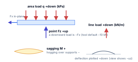
| Entry | Positive direction | Stored as |
|---|---|---|
Point Fz vertical |
up | as entered (down = negative) |
Point Fx,Fy |
+X, +Y | as entered |
Line Vertical (kN/m), + down |
down | negated into fz |
Line In-plane Fx/Fy |
+X, +Y | as entered |
Area Pressure q, + down |
down | pressure positive down |
Area Fz vertical |
up | as entered |
Wall Top line load |
down | absolute value |
| Self weight | down | generated |
| Reactions R↓ | magnitudes; ground total signed with + up |
Two common mistakes: entering an area load as −3 kPa (it acts upwards), and
entering a point load as +10 kN Fz (it acts upwards). The dialogs state their
convention in the label and tooltip.
3.6 Display and editing
- The loads arrows toolbar toggle shows/hides all load glyphs (adding a
load switches them on automatically). Glyph colours follow the case colour;
the label showsq = …for area, the force/moment for point loads and the
magnitude for line loads. - When a combination is active, magnitudes are the factored values and
zero-factor cases are hidden. - Edit a single load in the Properties pane; change the case of many at once
with the bulk editor. - Delete loads from the model tree (Loads group) or by selecting them and
pressing Delete. Deleting a slab deletes loads attached to it. - Loads are not draggable - edit X/Y or redraw.
What invalidates results
Editing any load marks the results stale (Results stale badge); a structural
change (geometry, mesh, design-heavy edit) clears them outright. Re-run the
analysis after changes.
3.7 Analysis load selection
In the Run analysis modal, Step 2 - Loads lists every case and
combination with a checkbox each; all are ticked on first open. The text input
(IDs e.g. 1, 2, c1 or all) and the All / None buttons drive the same
selection. The counter reads N of M cases · K of L combos selected.
Each row also has a Sustained / Short-term selector for the long-term run:
- a case keeps its own flag;
- a combination marked Short-term is treated as wholly instantaneous
(no creep or shrinkage), overriding its cases' flags for that combination.
Every ticked item is solved and becomes a selectable result set; with two or
more sets an Envelope: max and Envelope: min set are built
automatically (per node, element, reaction and beam station).
Practical selection: solve the SLS combinations for deflection/cracking and
the ULS combinations for strength design; solve load cases individually when
you want to inspect one load effect.
3.8 Worked load takedown
Flat plate 8 × 8 m, 200 mm, C32, ρ 2400 kg/m³.
Self weight: 2400 × 0.2 × 9.81/1000 = 4.71 kN/m². With the SW case
ticked, the model total is 4.71 × 64 = 301.4 kN.
Superimposed dead: services + finishes + partitions = 2.5 kPa →
160 kN total.
Live: 3.0 kPa → 192 kN total.
Service combination (EC2, G + Q): 4.71 + 2.5 + 3.0 = 10.21 kPa →
653.4 kN.
ULS 1.35 G + 1.5 Q: 1.35 × (4.71 + 2.5) + 1.5 × 3.0 =
9.73 + 4.50 = 14.23 kPa → 910.9 kN.
Checking in the app: solve the ULS combination, open Column reactions (R↓)
and read the Applied ΣFz row (or the equilibrium residual in the analysis
summary) - it should read ≈ −911 kN for this model. The verification model
col-four-udl uses exactly this check (640 kN at 10 kPa on 64 m²).
3.9 Pitfalls and checks
- Clear All is model-wide. The dialog buttons remove every load of that
type across all cases. There is no undo. - Presets don't wipe old load records - verify the model after replacing
cases. - A load added while a combination is shown is refused; switch back to a
case first. - The active case selector tints everything - if loads seem missing, check
whether the active combination has a zero factor for their case. - Area load
qis per square metre over the drawn polygon, not over the
slab; the target line shows the polygon corner count. - Equilibrium is the first check. In the analysis summary, ΣRz should
equal the applied vertical load. If it does not, a load is not reaching the
mesh (island, stray point load inside an opening, or a polygon outside its
slab).
→ Next: Chapter 4 - Analysis